|
The
DS-Line converter allows performing a scan of the very low frequency
(VLF) range. Bugging devices can use these frequencies to transmit
acoustics through any wire out of a room or building. A standard
receiver cannot detect these bugging devices as it does not cover
the VLF range and cannot be connected directly to a telephone or
an AC wire. The optional DS-LINE converter converts the VLF range
up to the range covered by the receiver and performs voltage regulation
- this enables the receiver to process and demodulate VLF signals.
The
converter allows the operator to perform the following:
- To
test telephone lines, alarm wires, AC wires and mains for the
presence of accoustic-modulated signals in the range 5 ĻHz-2 MHz
- To
test an area for the presence of infra-red beams which may be
produced by a bugging device (the probe is optional)
- To
test the electromagnetic field near constructions and items in
order to detect electronic equipment inside (the probe is optional)
- To
test an area for the presence of ultrasonic sounds which may be
produced by a bugging device (the probe is optional)

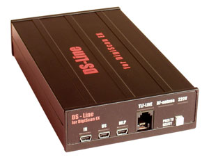
Picture 1. View of the DS-LINE

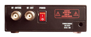
Picture 2. Rear panel
The
converter has 6 sockets:
- 'RF
ANTENNA' - input for connecting the receiver's antenna
- 'RF
OUT' - output for connecting to the receiver's antenna input
- 'TLF-LINE'
- input for connecting to telephone lines, alarm wires or any
other wires with the voltage below 150V
- 'IR'
- input for connecting the IR-LINE infra-red probe (optional)
- 'US'
- input for connecting the US-LINE ultrasonic probe (optional)
- 'MLP'
- input for connecting the MLP-LINE electromagnetic field probe
(optional)
The
input is choosed manually by the operator. When leaving or entering
the VLF range the operator is offered to choose the proper input.
If the general range is to be checked the operator chooses 'RF-ANTENNA'
input. (Note: AC wires are tested through the unit's power lead).
Algorithms
of work
Preparation
1. Carry out standard connection of the receiver
2. Connect the receiver's antenna to the converter's 'RF-ANTENNA'
input
3. Connect the output 'RF-OUT' to the receiver's antenna input using
the lead supplied with the DS-LINE
4. Switch on the converter using the 'POWER' button on the rear
panel
5. Open the 'Parameters' window, choose the 'Other' page of the
tab bar, enter the converter heterodyne's frequency in the corresponding
line and press 'OK'.
Checking
AC wires
1. Press the 'SELECT' button a few times on the front panel of the
converter to select '220V' input
2. Choose the 'VLF scan' command in the DigiScan EX program. A reminder
message 'Connect the VLF converter' will appear. Press 'OK' to start
scanning.
3. Tune in each peak in the bandscope which appears after scanning
and listen to the signal in order to detect the acoustics of the
room. Use frequency (FM) and amplitude modulation (AM). Try changing
the volume of the computer's speakers and check for the appearance
of a tone signal which may be a result of a working bugging device.
4. Check all peaks in the VLF range's bandscope - from 5 kHz to
2 MHz
5. Acoustics usually spreads inside an AC phase; therefore it is
necessary to test every mains outlet in the room in case they belong
to different phases.
Checking
telephone wires
1. Press the 'SELECT' button a few times on the front panel of the
converter to select 'TLF-LINE' input
2. Ensure that the handset of the telephone is hung up
3. Connect one end of the telephone probing cable supplied with
the DS-LINE to the 'TLF-LINE' input and the other end to the wall
telephone socket or socket in the telephone using the supplied splitter.
Ensure that the telephone stays connected to the line after connection
4. Choose the 'VLF scan' command in the DigiScan EX program (the
'Mode' menu). A reminder message 'Connect the VLF converter' will
appear. Press 'OK' to start scanning.
5. Tune in each peak in the bandscope which appears after scanning
and listen to the signal in order to detect the acoustics of the
room. Use frequency (FM) and amplitude modulation (AM). Try changing
the volume of the computer's speakers. Pick up and hang up the telephone's
handset. Audible sounds or the appearance of a tone sound after
the volume increase may be a sign of a working bugging device in
the room.
6. Check all peaks in the VLF range's bandscope - from 5 kHz to
2 MHz
7. Repeat the procedure for each telephone line in the room
Checking
alarm wires
The sequence of actions is similar to 'Checking telephone wires',
except the telephone probing cable is connected to the alarm wires
via the supplied adapter. Before performing this procedure ensure
that your actions do not cause the alarm to activate.
Checking
infra-red range
1. Press the 'SELECT' button a few times on the front panel of the
converter to select IR-LINE' input
2. Connect the optional IR-LINE infra-red probe to the corresponding
socket of the converter
3. Since infra-red bugging devices work only in the line of sight,
windows are the most likely areas where possible infra-red beams
can be detected. Place the IR-LINE probe as close as possible to
the external side of a window and direct its sensor into the room.
4. Choose the 'VLF scan' command in the DigiScan EX program. A reminder
message 'Connect the VLF converter' will appear. Press 'OK' to start
scanning.
5. Tune in each peak in the bandscope which appears after the scanning
and listen to the signal in order to detect the acoustic of the
room. Use frequency (FM) and amplitude modulation (AM). Try changing
the volume of the computer's speakers. Direct the infra-red sensor
to different parts of the room. Audible sounds or the appearance
of a tone sound may be a sign of a working bugging device in the
room.
Options:
-
IR-LINE - infra-red probe
- US-LINE
- ultrasonic probe
-
MLP-LINE - electromagnetic field probe
- ANT-LINE
- wide-range antenna. Allows to avoid possible emissions from
a computer.
|
|
|
Picture
3. IR-LINE
|
|
|
|
Picture
4 . MLP-LINE
|
Specification
| Heterodine's
frequency |
4
MHz |
| Tested
frequencies on telephone lines, communications and AC wires |
5
ĻHz -2 MHz |
| Tested
frequencies in infra-red and electromagnetic range |
5
kHz - 600 kHz |
| Power |
AC
220V |
| Power
consumption |
5
W |
| Max
voltage (power lead input) |
250
V |
| Max
voltage ('TLF LINE' input) |
150
V |
|